[2008-05-21] Welded steel flask for green sand casting
If you're already a sand crab, then you know what this object is for. If not, I encourage you to investigate the process of home green sand casting of aluminum. There are several good web sites that give a good overview of the process, but the first that comes to mind is backyardmetalcasting.com. If you want to learn more you should order at least the first book in Dave Gingery's build-your-own-machine-shop series, which explains how to build a cheap home foundry to make parts in wood and then cast them accurately in aluminum melted down from scrap. You really won't believe how cheaply this can be done until you see the book.
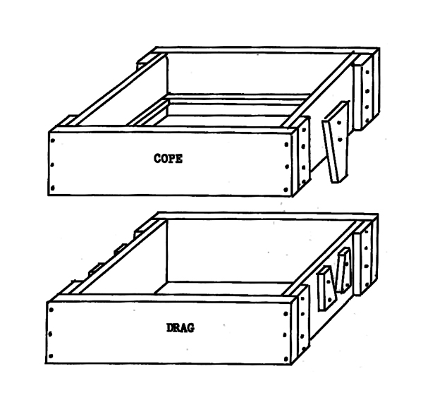
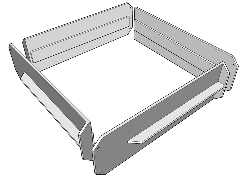
A more-or-less essential piece of equipment for this operation is a frame, in two layers, each of which holds and retains sand as it is packed around one half of the wooden pattern, and which includes alignment means so that the two layers can be separated, the pattern removed, and then the layers replaced in exactly the same relative position to accurately reproduce the pattern cavity. This frame is called a "flask," and it is commonly constructed of wood, essentially as shown below, with tabs and slots to provide reproducible alignment of the two halves, and protrusions of some sort on the inside walls of each half to help retain the packed-in sand against the force of gravity. This is by far the easiest way to make a flask, and for most purposes wooden flasks of this type are entirely adequate to the task.
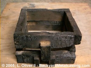
To paraphrase Gingery himself, however, it is the nature of a tool to improve itself. One relatively significant drawback of using wooden flasks in a metal casting operation is their inadequacy to the high temperatures involved. So long as the molten metal only contacts the sand, there is little danger, but in point of fact it's remarkably easy to spill some of the melt when trying to pour, using the necessary tongs, from a glowing-hot crucible into a 1 or 1.5" diameter sprue opening. Metal that misses the hole may well run off the sand and onto the flask, and at molten aluminum temperatures a wooden flask will begin instantly to burn. It doesn't explode or "burst" into flame, but even a small drip causes immediate charring and visible flame on the surrounding wood, and it takes quite a bit of huffing and puffing to get the area cool enough that it doesn't immediately re-ignite when extinguished. The picture below, from backyardmetalcasting.com, shows what tends to happen to a wooden flask after prolonged use.
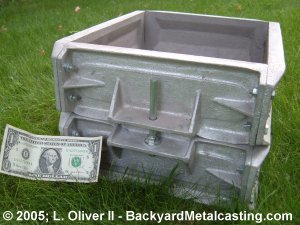
Some workers have suggested using temporary wooden flasks to cast sides for all-aluminum flasks. L. Oliver, Jr. has produced some really beautiful cast aluminum flasks of this type (shown above), and I myself have designed a single casting, shown below, that can be bolted together with copies of itself to produce complete flasks. The problem with this approach, however, is that cast aluminum is only marginally better than wood in terms of temperature tolerance, and in some ways may actually be worse. At the very least, an aluminum flask will not burn if you spill molten aluminum on it. However, and somewhat obviously, it will melt, at least in some small amount, and if the spill is large enough it may warp or even break from thermal stress. Considering the considerable extra effort involved in producing an accurate pattern and sand-casting it 8 times or more, the marginally improved performance of a cast aluminum flask over a simple wooden one doesn't really seem worth it.
On July 21, 2008, I received an e-mail from Mr. Oliver of backyardmetalcasting.com, in which he articulately defends the use of cast aluminum flask panels:
"...your fears about aluminum flasks are based on incorrect theory. The aluminum flasks do not melt when some molten aluminum is spilled on them (not even a little). Aluminum transfers heat better than most other metals so the heat is conducted away (into the air and the molding sand) faster than the metal flask panels can absorb it. The physical properties of aluminum makes it so that nearly the entire panel will have to reach 1200 degree F. before even a small part of it will melt. In fact I can pour molten aluminum directly into the recess of one of the flask panels and it won't melt. The heat is dissapated too quickly."
Mr. Oliver's been doing this a lot longer than me and I have no doubt that he is correct. My characterization of aluminum flasks as "only marginally better than wood" is probably unfair and inaccurate. Nonetheless, I still think that welded-steel flask construction has much to recommend it over cast aluminum, not the least of which is that it obviates the necessity of building a temporary wooden flask in order to cast sides for an aluminum one. Steel is easily fabricated and will resist indefinite exposure to any amount of molten aluminum, zinc, or bronze.
It was Tim McCreight's excellent reference The Complete Metalsmith that introduced me to the idea of making flasks from welded angle iron, and the more I thought about it the more sense it made. McCreight's book is targetted primarily at jewelers, however, and the angle-iron flask design he demonstrates, and which I've duplicated, has perhaps only a single drawback, which is limited flask depth. If you took this same approach to building a flask that was, say, 12" deep in total, and would thus require 6" cope and drag sections, you'd be talking about using pieces of angle iron 6" across the hypotenuse, or better than 4" on a side. Angle iron of that size, of course, is extremely heavy. Depending on the X and Y dimensions of the flask you need, you might still be able to move the empty cope or drag by itself, but when it was loaded down with greensand you might well need a crane.
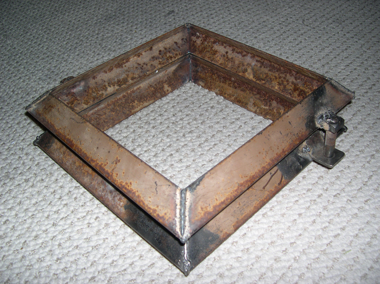
For my own purposes, however, the casting I do rarely calls for thick cross-sections, and the 4" total depth this flask provides (2" each for the cope and drag) is plenty. I chose a perfectly square shape for ease of manufacture. Exterior dimensions are 12" square, while the opening is 9.75" square. The total empty weight is 8 lbs. The angle iron was cut from a discarded bedframe with an abrasive chop-saw; the flats are 1.5" long and 3/32" thick at the edge. Alignment tabs were cut and bent from scrap 2" strap, 5/32" thick. Square nuts and matching carriage bolts were from the junk bucket. The bolt shafts are 0.5" thick and the square nuts are 0.75" on a side.
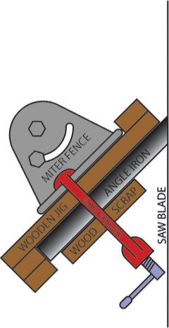
Eight 12" angle iron members were cut for the cope and drag sides. A stop block was clamped to the saw base, along the squared-off mitre fence, with 12" between it and the near edge of the abrasive disc. The angle iron was held square against the fence with the free hand while the chop saw was operated 8 times, and the ends deburred using a bench grinder equipped with grindstone and wire wheel. Do not skip the deburring step, and be very cautious when performing it, as fresh-cut steel burs are razor-sharp. Paint and rust were removed from the surfaces to be welded at the deburring stage, using the wire wheel. Hand, eye, and ear protection were used and are necessary during all cutting, grinding, and polishing operations. The chop saw's mitre fence was then adjusted to a 45-degree angle, which was checked against an accurate angle held between the fence and the surface of the abrasive disc. The ends of the angle iron members were then mitred at 45 degrees using an improvised wooden jig as shown below.
Welding was accomplished using a small flux-wire welder from Harbor Freight ($149.99 as of this writing.) This machine, which features automatic feeding of welding wire, is by far the easiest way to weld anything that I've ever encountered. If you're intimidated by welding, the flux-wire welder can help you get over it. While you're at the store, pick up an autodarkening welders visor (also a steal at $59.99), and a magnetic welder's clamp ($5.99).
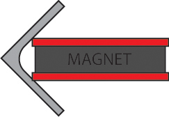
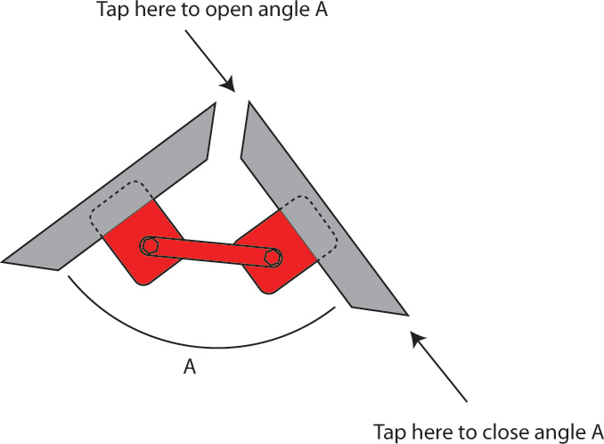
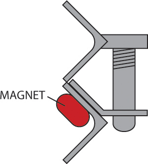
One of the keys to accurate welding is clamping the pieces to be joined accurately beforehand, and the primary concern in welding up the cope and drag frames is that they both be flat as possible, so that they will meet evenly at the parting plane. The first two mitred angle iron members were selected and their mitres aligned using a magnetic welding clamp positioned on the inside of the angle. The assembly was laid on a flat polished concrete garage floor, and the angle between the two members checked against a carpenter square and adjusted by changing the position of one of the magnets along its member by tapping with a rubber mallet, as necessary, to achieve a square corner when the two mitred faces were brought together. A light tack weld, right at the point of the mitre, was used to fix each joint during initial assembly. To this two-member assembly, a third side was added in the same fashion, removing and repositioning the magnetic clamp on the new corner and adjusting to square as before.
Both cope and drag were completely assembled in this manner, and then checked against each other for alignment. When this proved satisfactory, the joints were welded completely along their lengths, alternating beads across the diameter of each frame, and also between the two faces of each frame, with each weld, in an effort to more evenly distribute the thermal stress. Make sure to peen the fresh beads (that is, whack them and the steel immediately around them with a sharp hammer) as they cool, again in order to help relieve thermal stress that the welding operation can generate. The alignment of the two frames was checked again once they'd cooled, and found again to be satisfactory. Some 1/8" holes that had been previous drilled in the angle iron, and subsequently incorporated into the frame assemblies, were quickly and easily filled with the flux-wire welder.
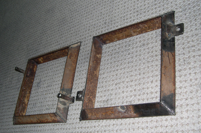
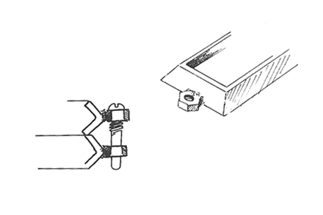
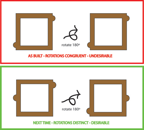
One frame was chosen more-or-less-arbitrarily, as the cope, to bear the male halves of the alignment assemblies, the pins. Two ~0.25" flats, ~1" wide, were ground, using the bench grinder, on the point of the angle iron on opposite sides of this frame, as shown below, to make contact points for the square nuts. These were ground by eye to be as close to orthogonal to the plane of the frame as possible, but it did not have to be very precise and was not. And here I think I made one small mistake, that I would change if I were to do it again. Notice that the the pins have been positioned symmetrically, caddy-corner to one another, on the cope. This pin arrangement is less than ideal, because there are two orientations in which the cope and drag could possibly fit together to the casual observer, but only one of which will be accurately aligned. See the left drawing, below. A better arrangement is shown to the right, in which one pin is centered on its side and the other is positioned on the opposite side, near the corner. With this arrangement, there is no confusion about which orientation the cope and the drag are to interlock with one another. It would have been better to do it this way.
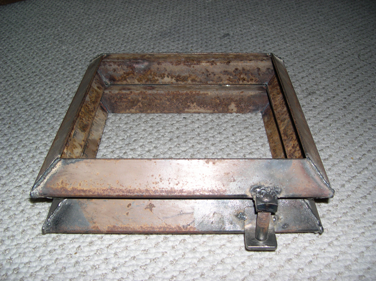
With the mounting flats ground, for better or worse, the square nuts were cleaned on the wire wheel and clamped against the ground flats in a bench vise before being welded in place, on all edges. The heads of the two matching carriage bolts were then cut off on the bench grinder, leaving rods, threaded for about an inch on their ends, about 2.5" in total length. The cut ends of the bolts were deburred and rounded slightly on the bench grinder. The threaded ends of these rods were then screwed into the attached nuts until their ends were flush with the upper nut faces, and welded in position on the upper side. This welding is probably not necessary for proper operation, and indeed being able to remove the pins may be handy in some instances, but I did not want to risk losing them in storage and preferred the security of welding them in.
All that remained was to mount the female halves ot the alignment assemblies on the drag. And here's where accuracy starts to be important. An error at this stage could cause the pins to stick or strain during insertion or removal (which can cause catastrophe with a cope full of sand), or worse still, to not interlock at all. Two 1.25" tabs of 2" steel strap, 3/32" in thickness, were cut on the chop saw, and their edges deburred and rounded and cleaned on the bench grinder. They were then clamped into a vise, with half of their lengths protruding above, and bent to 45 degrees by pounding the exposed length with a 2-lb hammer. The angle was eyeballed against an accurate gauge. The resulting bends divide each tab into two sections. A 1/16" lead hole was drilled in the approxiate geometric center of one section on each tab, and step-drilled up to 0.5". Holes were deburred with a conical angle-grinding bit mounted in the drill press. The fit of the holes was tested against the pins and found to be adequately free but without too much play (<1/32").
Final assembly of the flask consists of tack-welding these tabs in place. First, the cope and drag were properly aligned with one another and clamped in that position. Then the tabs were slipped over the pins, with the pins passing through their respective holes, and the bent section of each tab positioned flat against the slope of the cope's angled side. In this arrangement, the section of each tab bearing the holes is approximately perpendicular to the parting plane. The weight of these free extending sections tended to cause the bent sections to pull away from the flats of the angle irons where they would be joined, and this problem was alleviated by securing the bent sections against the flats by means of strong magnets positioned on the interior face of the angle irons, as shown. With everything positioned and properly aligned, each tab was tack-welded in place at two points against the angle iron. These tack-welds were judged to be sufficiently strong for alignment purposes; complete beads were foregone due to the risk of warping under heat. The resulting cope and drag align effortlessly and with extremely little play.
last modified 2008-07-21